
Understanding and Eliminating Electrode Overlap Issues
Understanding and eliminating electrode overlap issues
Samson Teclemariam | Mechanical Engineer, UKBIC
What is electrode overlap and why does it matter?
In lithium-ion cell manufacturing, electrode overlap refers to the region where the active areas of the anode and cathode are aligned across the separator as shown in Figure 1. Maintaining adequate overlap, whereby the anode active area overlaps the cathode, is critical to achieving uniform current distribution and consistent electrochemical performance.
Poor electrode overlap occurs when the active areas of the anode and cathode are misaligned, typically when the cathode overlaps the anode, creating regions where one electrode is not fully opposed by the corresponding counter-electrode. This condition is commonly known as the electrode overhang defect. Poor overlap can lead to localised current-density hotspots, lithium plating, accelerated ageing, reduced cell performance, and an increased risk of internal short circuits.
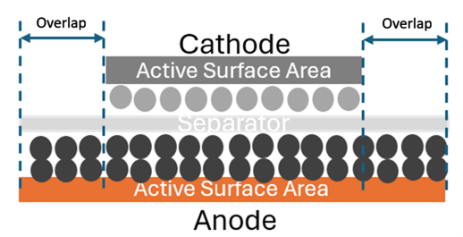
Figure 1: Schematic view of a battery cell with anode overlap. Instances where the cathode extends beyond the anode is called the electrode overhang defect.
What causes poor electrode overlap?
Design-related origins of overlap issues
Electrode dimensions are defined during cell design, with the anode typically designed to extend beyond the cathode by a controlled margin to minimise the risk of cathode overhang. If this design margin is insufficient, normal manufacturing variation may result in regions where the cathode extends beyond the intended overlap area.
Tolerance stack-up is a common design-level contributor to overlap issues. Even when nominal dimensions appear acceptable, variations in electrode length, coating position, separator dimensions, and assembly alignment can accumulate, reducing the effective overlap and creating unintended overhang regions.
One of the most significant risks associated with severe electrode misalignment is the increased likelihood of an internal short circuit. In extreme cases, an internal short can initiate thermal runaway, potentially resulting in cell venting, fire, or explosion.
Manufacturing stack-up and process induced overlap issues
In practice, electrode geometry is influenced by multiple process tolerances. An example electrode is provided in Figure 2, where there is a continuous coating and mass free edge. This electrode type can apply to pouch, prismatic and tabless cylindrical cell formats ahead of assembly. Sources of variation include machine slitting accuracy, particularly when manufacturing more than two electrodes from a single coated sheet (dimension C in Figure 2), coating width variations and straightness (dimensions B and D in Figure 2) and the mass free edge width variation (dimension E driven by dimensions A, B and coating positional accuracy). When these variations combine, they create a tolerance stack-up that can significantly deviate from the intended design, increasing the likelihood of overlap defects and reducing manufacturing yield.
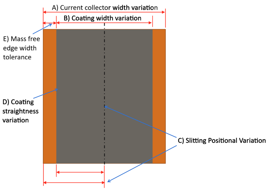
Figure 1: Schematic view of an anode electrode showing sources of variation by the time the final electrode form is ready for cell assembly.
Design and manufacturing interface
Robust electrode design requires a clear understanding of how design intent translates into manufactured reality. By accounting for both design and process tolerances, engineers can predict worst-case alignment scenarios and avoid unintended overlap. Root Sum Square (RSS) tolerance analysis provides a systematic way to evaluate these combined effects, enabling more reliable and manufacturable electrode designs.
At UKBIC, we have developed an RSS-based tolerance calculator to assess all potential stack-up scenarios across electrode design and manufacturing processes. This approach allows engineers to quantify alignment risk before production, optimise electrode dimensions for manufacturability, improve yield, reduce scrap, and ensure consistent cell performance.
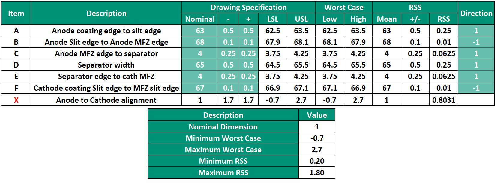
Table 1: Tolerance stack-up illustration
Table 1 illustrates how the tolerance stack-up is performed in accordance with the design shown in Figure 3 for a tabless cylindrical cell electrode. The dimensions presented are for illustrative purposes only and do not represent a real-world design. The parameter tolerances in Table 1 should be further refined through an understanding of manufacturing equipment capabilities at the relevant process steps.
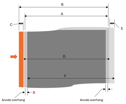
Figure 3: Schematic view of a battery anode electrode for a tabless cylindrical cell
Key takeaway
Electrode overlap issues arise from the combined effect of design assumptions and manufacturing tolerances. By incorporating tolerance stack-up analysis during the design phase, engineers can minimise misalignment risk, improve yield, and ensure consistent electrochemical performance. Tools such as RSS-based modelling enable robust, manufacturable electrode designs. However, an understanding of manufacturing capabilities should be gained to inform such tools.
About the Author